 |
The home of the VMCC AJS OHC Register |
|
NOTES ON REPAIRS TO A.J.S. MOTOR-CYCLES
By W. Stevens (A. J. Stevens Ltd.) with additions from list members
Part 1. The Engine.
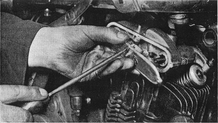
Fig. 1. REMOVING ROCKER-BOX COVER.
Figure 1 Shows an o.h.v. engine with the push rods removed. It will be noticed that two springs are fitted behind the cover to prevent side movement of the rockers. Whilst taking out the last pin from the rocker box, press on the cover to relieve the pressure of the springs on the latter.
Various changes in design have been made from time to time, embodying detachable cylinder heads; plain, roller and ball main bearings; plain and roller big-end bearings; semi-automatic, mechanical, dry and wet sump lubrication systems.
Cylinder Heads
On engines up to 1927 both cylinder and head were held down by means of a bridge piece across the cylinder head and two long bolts attached to the crankcase ; or, in the case of the o.h.v. models, with a stirrup strap for the head, and left- and right-hand thread sleeve nuts between the former and studs in the crankcase.
In these cases, when removing or toghtening down the head ease or tighten the nuts evenly, and do not screw the head down too tightly, only sufficient to make compression tight.
On later models the cylinder barrel was held down from the foot by means of four studs and nuts on the crankcase and the head on the cylinder barrel by four or more pins screwed into the latter.
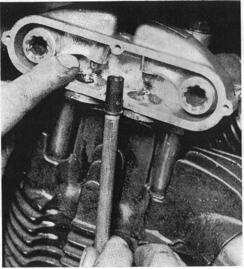
Fig. 2 Rocker box cover removed for inspection of rocker studs and push rod ends
Removing Cylinder Head
The simplest method of removing a detachable head, after the holding down attachments etc., have been removed, is to insert a screwdriver or similar tool between the top cylinder fin and the heas, prising the
latter carefully off the cylinder from both sides - prising upwards not downwards, or the radiating fins may be broken
(Fig 3).
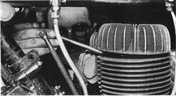
Fig. 3 - Method of removing cylinder head - prise off with a screwdriver. This should be done from both sides of the head, prising upwards not downwards
O.H.C. Models - Most Important
In the case of Overhead Camshaft Engines, when the cylinder or head only is removed, it is important that the camshaft sprocket and driving chain should be supported and not allowed to drop in the chain cover while the engine is being revolved. A piece of wire to prevent this happening can be hooked through the sprocket and fastened to one of the sprocket cap pins screwed into the top of the chain cover (fig. 5)
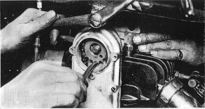
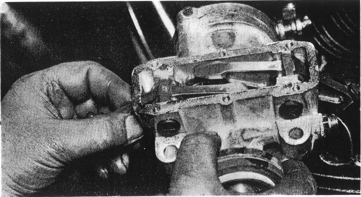
Fig. 4. Removing O.H.C. Cambox. The camshaft chain and sprocket should be steadied when doing this
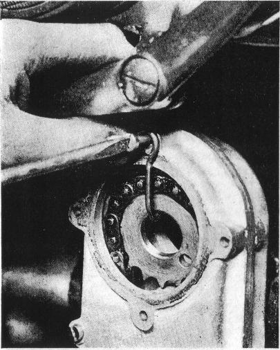
Fig 5. With Overhead Camshaft Engines - Chain and Camshaft sprocket securely supported by a wire hook to prevent them falling in the timing cover should the engine be removed.
In removing the cylinder or head on these engines, it is first necessary, after taking away the exhaust pipe, carburetter, oil pipe to cambox, etc., to remove the cap secured to the top of the chain cover by four pins. Take out the split cotter from the nut on the camshaft, remove the nut and washer, and after removing the four pins holding the cambox on to
the head, carefully take away the former whilst the sprocket is being steadied. An assistant will be useful during this operation.
The sprocket and chain should then be supported by the method already mentioned .(Fig. 5).
Compression Ratio should be altered only by changing Piston
It will not be out of place here to point out that on camshaft engines the compression should not be raised by taking any metal from the bottom or top of the cylinder, or the compression lowered by fitting a thicker washer to the cylinder foot, as this will alter the camshaft driving-chain centres. The makers' advice should be sought on this matter, as special pistons are supplied by them for the above purpose.
Making a Head Joint
Where cylinder heads are held down by means of pins screwed into the top of the cylinder barrel, refitting of the head will be simplified if the head washer is coated with a thin film of oil or vaseline and placed in position on the top of the cylinder. This will prevent the washer moving about during the fitting of the head, and possibly damaging the former when the holding-down pins are inserted.
O.H.V. Tappet Tubes
On o.h.v. engines where rocker boxes are fitted, the push rods are enclosed by
tubes, and to get at the former the lock nuts on either end of the inside the other
are unscrewed and the tubes telescoped one inside the other. To remove the push rods on all o.h.v. engines, special extractor tools are supplied by the makers. Two types have been used (see fig 8).
Pistons
On engines where cast-iron pistons have been used, the gudgeon pin was held in position by a thin steel band fitting in a groove.
On earlier models with aluminium pistons the gudgeon pins were held in position with a split cotter, and on later models with aluminium pistons
Fig 6 - Cambox cover removed for inspection
 by means of small spring retaining rings inside the gudgeon-pin hole on either side of the piston. In assembling care should be taken to see that in the case of the steel band fixing, this is below the outside diameter of the piston.
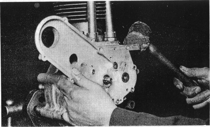
Fig 7 - Removing the timing cover - tap lightly at the back or top with a mallet, at the same time pulling the cover away and keeping it square with the crankcase.
Always renew Gudgeon-Pin Fixings
In the case of the split-cotter fixing, the Original cotter should never be refitted. Always use a new one. The same applies to the springretaining rings where these are used, and special ,are should be taken to see that both these are fitted, as it is quite easy when repairs are being hurried forward for one to be missed. Also see that the retaining rings snap properly into their grooves, as if not, damage will be done by the
gudgeon pin forcing the retaining ring against the cylinder wall.
Fig. 8.-PUSH-ROD EXTRACTOR.
Valve Timing
The correct setting for the valve timing on all A.J.S. engines is clearly marked on the timing wheels, as shown in Figs. 12 and 12A.
Fig 9. Using Valve Extractor.
This illustrates how to use a screwdriver in conjunction with the valve extractor to prevent the valve cone from canting on the stem. If this is not done an undue strain is put on the tool, which becomes distorted, as indicated by the dotted lines, and so loses its effectiveness.
Singles
In the case of single-cylinder engines, the small timing wheel is stamped in one position with one dot, and in another position with two dots, these registering with similar marks on the inlet and exhaust camwheels.
Twins
In the case of twin-cylinder e n - gines, there is an additional double camwheel w h i c h operates the two inlet valves. This double camwheel is marked with a registers with a similar "dash" on the front exhaust camwheel.
O.H.C Models
On overhead camshaft engines the small timing wheel is stamped with a dot which registers with a similar mark on the magneto driving sprocket. On this sprocket also is an arrow opposite the dot, which points to another arrow on the camshaft sprocket.
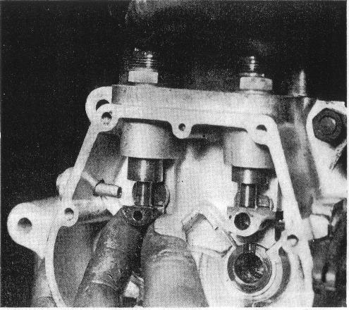
Fig 10 - Examining for Excessive Clearance between the Foot of the Tappet and the Stud at the back by twisting the Former with the Fingers.
Main Bearings
Where plain bearings are fitted, and in case they have to be removed, fi r s t examine to see if a fixing screw is employed, as this should be taken out before the bush is driven out of the crankcase or otherwise damage may be done.
Big-end Bearing
If the flywheels have been completely dismantled,take care in assembling that a location peg is fitted to the crankpin, which registers with a slot in the flywheel.
This is important as the peg sets the position of holes drilled in the crankpin and up the web of the flywheel for oil feed to the big end bearing.
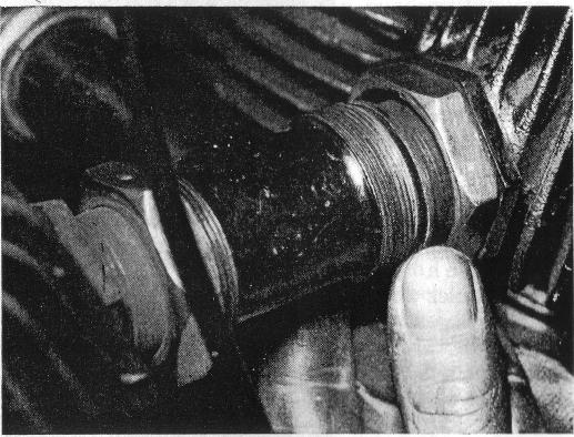
Fig 11 Making Airtight joints on Twin Engines between the Induction and Inlet Pipes
Slack off the locknuts on the inlet pipes which are screwed into the cylinder. Screw out the pipes until their faces are flush with those of the induction pipe, leaving no gap. The induction-pipe lock nuts should then be tightened up and afterwards the inlet-pipe nuts.
Ignition Timing
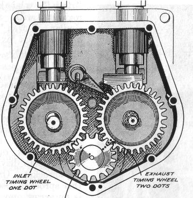
Fig 12.-Correct Setting of Timing Wheel on Single-Cylinder Engines
Fig 12a - Timing Wheel Setting on Twin Cylinder Engines,
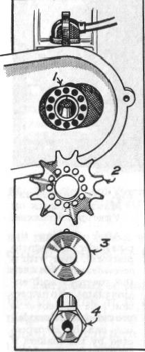
Fig 14 - Magneto Timing - Vernier Ajustment.
1. Magneto Sleeve, 2. Magneto Sprocket, 3. Peg Washer, 4. Sleeve Lock Nut
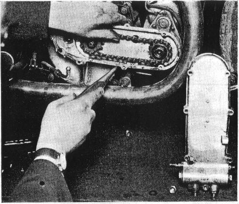
Fig 13a - Adjusting Magneto Chain on Vertical Engines
After slackening the pins under the magneto platform, lever with a screwdriver between the magneto and engine plates. No inspection hole and cover is provided with this model, but can be incorporated by the makers if required.
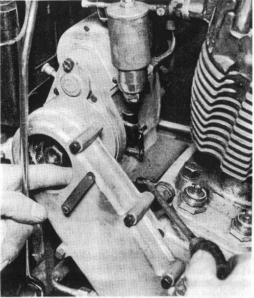
Fig 13-Adjusting Magneto Chain on Inclined Engines
After the nuts on side of the platform have been slacked off, lever the latter up from the front. Note the chain inspection hole
All A.J.S. engines are provided with vernier adjustment. Fig. 14 shows this arrangement, a description of which might be useful.The engine magneto driving sprocket is secured to its shaft by means of castellations which render wrong replacement impossible. The sprocket on the armature shaft ofthe magneto has a vernier adjustment which allows a very accurate and certain method of fixing the drive after the correct setting has been arrived at.
The setting of this vernier adjustment might sound a trifle complicated, but in reality it is quite simple. Fitted to the armature shaft on the magneto is a sleeve
which has thirteen holes in a circle. Fitting over the collar on this sleeve is a magneto sprocket which has twelve holes similarly arranged.On both the engine and the magneto sprockets will be found an arrow. These must point to each other when fitted in the chain.
To do this, turn the engine over until the arrow on the driving sprocket is pointing directly towards the arrow magneto sprocket. The latter should be held free in the fingers and moved a tooth backwards or forwards in the chain until the correct setting is arrived at. Having done this, place the magneto sprocket on the sleeve and turn the armature shaft of the magneto until the mark found punched over one of the twelve holes on the sprocket registers exactly with a similar mark on the outside of the collar of the sleeve. It will now be found that the marked holes in the sleeve and sprocket respectively coincide, and the peg washer can be pushed into these holes, which effectively prevents the sprocket from moving from its correct setting when the sleeve lock nut is screwed up, without the possibility of the timing moving in the process, as is the case sometimes with other methods.
As a means of verifying the timing, or if retiming is necessary on account of the sleeve having been disturbed, on the magneto armature shaft, the piston should be set its correct distance from the top of the compression stroke in the ordinary way, and the sleeve lock nut and peg washer should be removed. This will leave the armature shaft free from the engine drive, but still connected by the chain to the engine. See that the sprockets have their arrows facing each other, as previously mentioned, and that the marks on the sleeve collar and magneto sprocket register with each other. Set the contact-breaker points, fit the peg washer in the marked holes already mentioned, and tighten up the sleeve lock nut.
If the drive has been fixed up as before detailed, when dismantled at any time it can be put back without retiming.If the one hole in the sleeve and in the magneto sprocket do not happen to be marked, it is well worth adding them, for reasons which will be obvious from the foregoing.The vernier adjustment also provides a speedy means of altering the timing. First, remove the sleeve lock nut and peg washer from the magneto sprocket. Now, if the timing is to be advanced, fit the peg washer in the next hole to the left. This will advance the timing 1/32 inch. Fitting the peg washer in the next hole will give another 1/32 of an inch and so on. To retard, work in the opposite direction.