| The home of the VMCC AJS OHC Register |
|---|
| Home | History | Sales | Wants | Newsletter | Gatherings | Photos | Links |
|---|
| Repairs | Engine | Gearbox | Clutch | Wheels and Frame |
|---|
Fitted to the brake drum are six permanent driving studs, three of which are short and plain, acting as dummy drivers, and the other three longer and screwed.
On one flange of the hub are six holes corresponding in position with the six studs on the brake drum. On the other flange of the hub are six larger holes, corresponding in position with the holes on the opposite flange. The wheel is fitted to and driven by the above six studs, the hub being held securely to the brake drum by means of three sleeve bolts passing through three of the large holes in the one hub flange, and screwing on to the three driving studs in the brake drum.
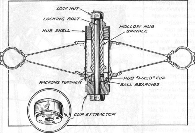
A centre spindle, screwed at the end, passes through the hollow spindle of the hub and engages with an internally screwed dummy bearing in the brake drum, which locks the whole up solid. Inside each of the three larger holes in the hub flange, through which pass the sleeve bolts, is a narrow groove, and near the end of each sleeve bolt is a spring-loaded ball. Should the sleeve bolts become loose, they are prevented from unscrewing right off the driving stud by the ball in the sleeve bolt dropping into the groove in the hole in the flange.
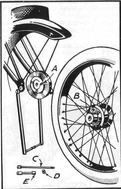
To remove the wheel from the drum first unscrew the three sleeve bolts right out, next the centre spindle, together with the distance piece, the space left by the latter enabling the wheel to be drawn off the driving studs. This leaves the drum supported in the frame by the dummy bearing. The above applies to front and r e a r wheels where they are interchangeable. In refitting reverse the operation.
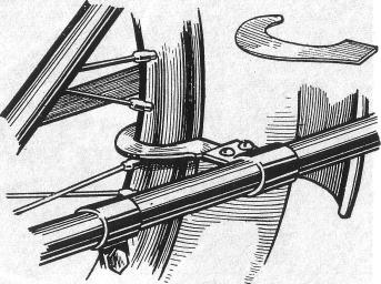
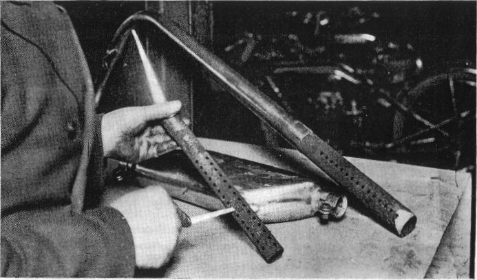
On later models this cup was secured by means of a lock ring in the same manner as the cup on the other side of the hub.On those hubs where the brake side cup is " fixed " it is a difficult matter to remove it, owing to the fact that, as has already been mentioned, it is reeled in, and the removal and replacement, if this is necessary, should in the ordinary way be undertaken by the makers. A tool, however, can be supplied by them for the above purpose, or if the necessary facilities are available for making one, a tool can be made to remove and replace the cup quickly and effectively (see Fig. 19).
In the case of the taper roller-bearing hubs there are one or two important points which should have careful attention when the bearings are being dismantled or assembled.
To dismantle release the locking nut and screw out the adjusting plate containing the felt washer and plain plate will then drop out.
Take out the spring ring from the opposite side of the hub and remove the felt washer and holder, consisting of two plates and retaining ring (the latter being between the two plates). The hollow spindle can then be pressed or driven out from either end , bringing with it one ofthe outer races, the other can then be pressed or driven out.
After examination has been made, if any excessive wear has taken place on the races of the spindle itself, a complete bearing should be fitted. No attempt should be made to remove the cage holding the rollers, or damage will be done, as these are fitted by a special process. No component part of the complete unit are supplied, only the complete unit.
The outer race can now be pressed in until there is about one sixteenth of an inch endplay in the spindle, insert the plain plate and dished plate with the felt washer, screw in the adjusting ring, and gradually screw down until there is just a fraction of endplay in the spindle. This should be .001 inch. It is of the utmost importance that the bearings are not adjusted too tight, as this would ruin them in a few miles.
Having got this adjustment correct, the locking ring can be put on and tightened up, again taking care that the adjusting ring does not creep forward and make the bearings too tight.
On all A.J.S. machines, except very early models, the brakes are of the internal expanding type, the brake shoes being aluminium and operated by a cam and lever.
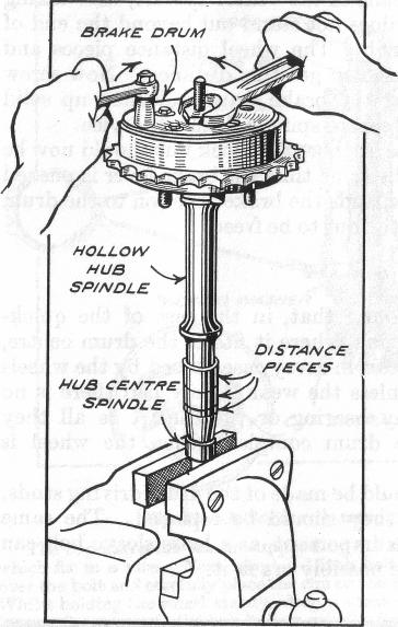
Assuming that the brake drum complete has been taken away from the machine, to dismantle to get at the shoes the anchor plate, to which is fitted the brake lever and shoe-expanding cam, must first be removed, and difficulty may be experienced in unscrewing the lock nut which secures the anchor plate to the dummy bearing of the drum (see Fig. 21).
llow spindle more than 1/2 inch. The wheel distance pieces and extra packing washers should be used to get this distance. Now screw the centre spindle up tight so that the brake drum is locked up solid to the hub and hold the end of the centre spindle firmly in a vice. With an open-ended spanner the anchor-plate lock nut should now be unscrewed (right-hand), whilst at the same time the brake lever is pushed hard forward. The latter action expands the brake shoes on to the drum and locks the whole solid, enabling the nut to be freed.
The difficulty in removing this lock nut is in most cases due to it having rusted up. If the following instructions are carried out the removal of the lock nut can be effected fairly easily in the most obstinate cases.
If the hubs of the wheels have not been dismantled fix the brake drum to the hub and secure by means of the centre spindle, first taking care to see that the centre spindle does not stand out beyond the end of the hollow spindle more than half an inch. The wheel distance pieces and extra packing washers should be used to get this distance. Now screw the centre spindle up tight so that the brake drum is locked up solid to the hub and hold the end of the centre spindle firmly in a vice.
With an open ended spanner the anchor-plate lock nut should now be unscrewed (right-hand), whilst at the same time the brake lever is pushed hard forward. The latter action expands the brake shoes on to the drum and locks the whole solid, enabling the nut to be freed.
When dismantled it may be found that, in the case of the quick-detachable wheels, the dummy bearing, where it fits in the drum centre, and the latter may show signs of wear, in every case caused by the wheels being run with slack bearings. Unless the wear is very bad there is no need to replace either the dummy bearing or the centre, as all they have to do is support the brake drum complete when the wheel is removed.
Careful inspection, however, should be made of the drum driving studs, and if the threads are not good they should be replaced. The same applies to the sleeve bolts. This is important, as a loose sleeve bolt can hammer the hub flange and in time possibly crack it. The screwed driving studs being a loose fit in the drum need not cause any concern, as they are held securely by the drum center and locked up solid when the sleeve bolts are tightened up.
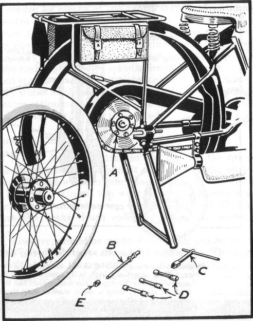
For checking the rear-wheel alignment in the frame after adjusting the chains, or if the wheel complete with brake drum has been removed, on machines from 1926 a device is fitted to the frame for carrying out the setting of the rear wheel quickly and correctly (see Fig. 22).
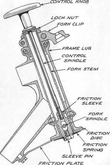
In this case (see Fig. 23) there is no need to remove the fork. First remove the pin securing the friction spring to the damper sleeve, which is inside the fork stem, next slack off a few turns the pin securing the friction plate to the frame lug and swing aside, this releasing the fabric friction disk. If it is required to dismantle completely, first unscrew the hexagon nut below the control knob which secures this to the fork stem and unscrew the control spindle right out. The nut on the end of the rear fork spindle, which passes through the fork stem lug should now be taken off and the spindle unscrewed out of the fork side plate or link, and withdraw from the lug about threequaters of its length. Do not take it right out.